
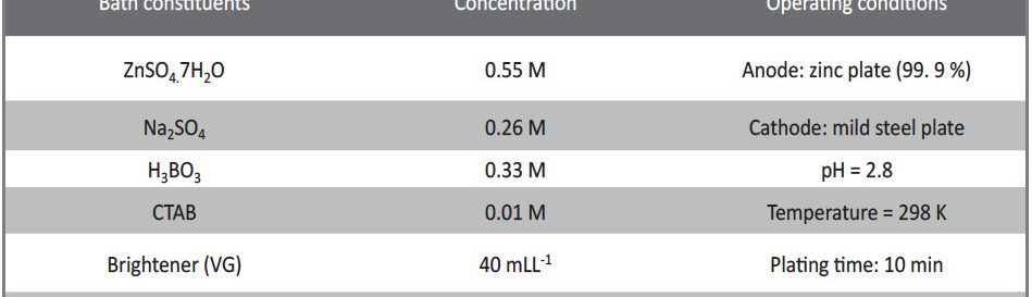
 Tab. 1: Optimized Zinc bath composition and operating conditions
The electrodeposition of zinc on steel was obtained from an acid sulphate bath containing condensation product formed between Vanillin and Glycine (VG). The bath constituents and operating parameters were standardized by Hull cell experiments. The investigation of electrodeposition and nucleation mechanism was carried out on graphite electrode using cyclic voltammetric and chronoamperometric techniques. The corrosion studies were carried out by Polarisation and Electrochemical impedance techniques, which helped to explore the good protection ability of the zinc coating in presence of VG. The surface morphology of the deposit was characterised by scanning electron microscopy. Increase in brightness of the zinc coating obtained on mild steel substrate was confirmed by reflectance studies. The phase structure and the preferred orientation of the zinc crystallites were studied by X-ray diffraction analysis. These studies revealed the influence of VG in enhancing the brightness and corrosion resistance of the zinc electrodeposit on mild steel substrate.
1 Introduction
Zinc coating is extensively used to protect and enhance the service life of steel due to its sacrificial nature. Bright finishing is always preferred than dull coating in industries, by considering its excellent durability and corrosion resistance [1]. Many researchers have reported that nanocrystalline or fine-grained bright coatings exhibit relative better corrosion resistance and other surface properties in comparison to those of the coarsegrained deposit [2]. Electrodeposition was found to be a versatile technique for producing nano -crystalline coating. Also, it is found to be technologically and economically viable production route to metals, alloys and metal matrix composites, both in bulk form and as coatings [3]. Properties of nano-structured electrodeposit such as hardness, corrosion resistance, wear resistance etc. are strongly grain size dependent [4]. The grain size of the electrodeposit depends on the deposition parameters such as pH [5], deposition technique [6], current density [4], substrate [7] and also on the type and number of additives included in the electroplating bath [8].
Numerous literatures are available on electroplating of pure zinc. In most of the studies, considerable attention has been given for the development of effective brighteners to generate smooth and mirror bright deposit capable of providing higher corrosion resistance [9]. A few researchers have tried to explain the role, mechanism and function of additives on parameters affecting the electrodeposition process of bright coating [10]. Based on the review of the earlier results, it is inferred that the additives are able to produce a bright deposit only when a) they are adsorbed on cathode surface b) they block the active sites c) affect the preferred orientation d) undergo electrochemical changes at the cathode surface e) increase deposition overpotential f) retard grain growth g) increase the nucleation rate [9]. The brightness of the deposit also depends on nature of substrate like surface roughness and unevenness. From the available literature, it is found that for large scale production of zinc plating, the electroplating bath contains one or more additives that invariably contain Nitrogen, Sulphur and Oxygen elements in their functional groups including aromatic and heterocyclic rings [11].
It is also confirmed from the earlier literature that the condensation product of aldehyde and amine is a good brightener than a single aldehyde or amine in the bath solution. This may be due to the presence of –CH=N- group in the molecule [12]. Hence, in the present work an attempt has been made to synthesize an additive i.e a condensation product from an aldehyde and an amine, which should be non-toxic, water-soluble, having stability at low pH value and hence can be conveniently used in acid-sulphate bath. Further, an investigation has been done to study the bath characteristics, effect of bath constituents and variables on the corrosion behaviour of zinc electrodeposit.
2 Experimental
The bath composition of zinc deposit is given in Table 1. The bath solutions were freshly prepared using analytical grade chemicals in double distilled water and used for the experiments without further purification. The standard Hull cell of 267 ml capacity was used to optimize the bath constituents. The Hull cell experiments were carried out without agitation. The pH of the solution was adjusted with 10 % by volume H2SO4 solution and sodium bicarbonate solution. The experiments were conducted at the room temperature (298 K). The anodic surface was activated each time by acid dip method in 10 % by volume HCl solution for 4-5 seconds followed by washing with running water. The mild steel cathode surface was mechanically polished with emery paper and degreased with trichloroethene and then immersed in 10 % by volume HCl solution to remove the dust and rust. The plates were then washed with running water, dried and then transferred to the plating bath solution for electrodeposition. After electrodeposition, the adsorbed impurities on the coated surface were removed by a bright dip in 1 % by volume HNO3 solution for 3-5 seconds followed by washing with distilled water and then dried with a drier.
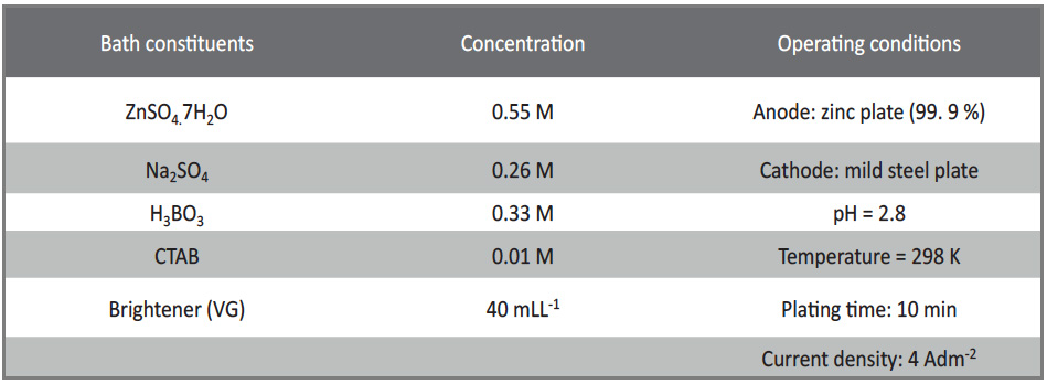
Tab. 1: Optimized Zinc bath composition and operating conditions
The condensation product was synthesised from equimolar amounts of Vanillin (1mM) with chemical formula C8H8O3 (AR grade, S. D fine chemicals) and Glycine (1mM) with chemical formula C2H5 O2N (AR grade, S. D fine chemicals) in Acetic acid medium, under reflux condition with continuous stirring for 3 hrs at 343K [13, 14]. The completion of the reaction was shown by thin layer chromatography (TLC). The resulting reaction solution was diluted to 100 ml with distilled water and a known amount of this solution was added to the plating bath solution. The bath solution with the condensation product (VG) was stirred for one hour before conducting the experiments to ensure proper mixing of the two solutions.
The cyclicvoltammetric and chronoamperometric studies were performed using CHI660D electrochemical workstation with a three-electrode system. A graphite electrode of geometrical area 0.02 cm2, a platinum wire and saturated calomel electrode were used as working, counter and reference electrode respectively. Before conducting each experiment, the working electrode was polished to a mirror finish with 0.05 μm alumina.
The corrosion behaviour of zinc coatings obtained from the plating bath in presence and absence of VG was studied in 3.5 wt. % NaCl solution by galvanostatic polarization method and electrochemical impedance spectroscopic technique, using the electrochemical workstation (Instrument model CHI660D). A three-electrode assembly was used. The working electrode (WE) i.e. zinc coated mild steel electrode was masked with lacquer to expose 1 x 1 cm2 area. A platinum foil was used as a counter electrode (CE) with saturated calomel as a reference electrode (RE), in the potential range of –0.8 V to –1.4 V and at a scan rate of 0.01 VS-1.
The surface morphology of the deposit on mild steel electrodes was examined using scanning electron microscope (JEOL-JSM-6400). The Philips X’pert PRO MPD X-ray diffractometer was used to determine the orientation of the zinc crystallites in the deposit. The preferred orientations of the crystallites in the deposit were determined by using the following equation [9].

Equation 1
Where, I (hkl) is the peak intensity of zinc electrodeposit and ΣI is the sum of the intensities ofindependent peaks. The index ‘0’ refers to the intensities for the standard zinc sample (JCPDS 00-004-0831). The orientation with maximumtexture coefficient value is the preferred orientationof the deposit [16]. The average grain size was calculated by using Debye Scherer’s equation,

Equation 2
Where k = 0.9, β is full width at half maximum, θ is reflectance angle and ʎ = 1.546 oA is the wavelength of radiation used [15].
The percentage reflection of deposits was determined using Ocean optics USB 4000 Spectrophotometer, referenced against a silver mirror. The reflectivity of silver mirror was set at 100 % and measurements were carried out at various surface points of the coated sample.
3 Results and Discussion
3.1 Electrodeposition process
The electrodeposition process was carried out in a trapezoidal container of 267 ml capacity called Hull cell. This standard Hull cell was used to optimize the plating bath constituents and the different bath parameters. The concentration of a particular constituent was varied continuously in small increments while keeping the concentration of other constituents as constant [2]. The concentration of a particular constituent or operating condition at which good bright deposit is formed over wide current density range was considered as optimum. The procedure was repeated for all the bath constituents and operating conditions. The optimised bath composition is given in Table 1. The basic bath gave coarse dull deposit between the current density range of 0.2–3 Adm-2 whereas the optimized bath gave bright deposit between the current density range of 0.5–5 Adm-2.

Fig. 1: Typical cyclo voltammograms of zinc coating obtained on graphite electrode from optimized zinc bath solution, 0.55 M ZnSO4 + 0.26 M Na2SO4 + 0.33 M H3BO3 + 0.01 M CTAB, pH = 2.78, Current density = 4 A dm-2, in presence (solid line) and absence (dotted line) of VG, in the potential range of –0.4 V to –1.7 V at scan rate of 0.05 VS-1
3.2 Cyclo voltammetric studies
The effect of VG on zinc deposition was studied using cyclo voltammetric technique. Figure 1 shows typical voltammograms obtained from the optimized bath in presence and absence of VG. The voltammetric response gives information regarding the components of the deposit and structure of the deposited phases.
The voltammogram shows an anodic peak at –0.91 V indicating the oxidation of zinc from η phase of zinc which is pure zinc phase. This result is in good agreement with the referred literature [14, 17]. The cathodic peak (E1) at –1.216 V is observed for reduction of zinc ions in absence of VG. The cathodic peak (E2) at –1.519 V is observed for the reduction of zinc ions in presence of VG and is associated with partial adsorption of VG on the cathodic surface. When VG adsorbs on the cathodic surface it blocks a fraction of active sites (θblocked), at which the first reduction of zinc ions occurs [14, 18]. As a result, the reduction of zinc ions occurs only at the remaining fraction of the active sites that are not blocked i.e (1-θblocked). Hence the cathodic potential associated with the reduction of zinc ions in presence of VG shifts to more cathodic potential when compared with its value in absence of VG. On reversing the sweep direction two current crossovers appear in the cathodic region of the voltammogram. The potential at which the crossover occurs at more cathodic region is known as nucleation over potential (Eη) and the second crossover at zero current region is known as crossover potential (Eco). The two crossovers are characteristic of three dimensional (3D) and subsequent crystal growth process. [19, 20].
The overpotential η = Ec – Eco, where cathodic peak potential (Ec) and cross over potential (Eco) was obtained from voltammograms. Table 2 clearly indicates that the overpotential value increases in presence of VG, due to adsorption of VG on the mild steel plate. With increase in overpotential (η), grain size decreases. Hence this result clearly depicts that VG is responsible for decrease in the grain size of the crystallites, which in turn is closely associated with brightness of the deposit. This result is found to be similar to the available data in literature [1, 21-22].

Tab. 2: The Cross-over potential (Eco), Cathodic
peak potential (Ec) and Overpotential (η) values
obtained from the cyclo voltammograms (Fig. 1).
This result suggests that VG is partially adsorbed on the cathode surface, resulting in reduction of the specific surface energy of the zinc nuclei, thereby reducing the radius and energy of the critical nucleus and enhancing the nucleation rate, which results in a finer grain structure and more compact bright zinc deposit.
3.3 Chronoamperometry / Transient analysis
This technique has proved to be a powerful means for explaining the mechanism of new phase formation (electro crystallization) [14, 23]. The chronoamperometric studies were used to identify the zinc nucleation mechanism at different potentials. The primary factor leading to the generation of fine grained deposit is the formation of fresh nucleation sites and their growth rate. For most of the metals, the charge transfer rate is high and continuous growth of nuclei formed is entirely mass transfer controlled. According to the theory, two types of nucleation can be considered based on the nucleation rate. In the first type, at increased nucleation rate all nuclei are instantly formed after the potential step and their number remains constant during the growth process. This is called instantaneous nucleation and is given by,

Equation 3
where I(t)= current density related to the geometrical area of the electrode surface, N is the total number of nuclei formed and K is the numerical constant calculated from

Equation 4
Where M and ρ are the molar mass and metal density, z F is the molar charge of the deposited species, D is the diffusion coefficient and c is the bulk concentration (mol / dm3).
In the second type, at small nucleation rate the nuclei are continuously formed during the entire time, before overlapping of the diffusion hemispheres around the growing nuclei is called progressive nucleation [14, 23]. In this type of nucleation, the metal clusters of different sizes are formed, especially at the initial time (t). It is described by,

Equation 5
Where Nο is the number density of substrate active sites, a is the steady state nucleation rate constant per site, K’ is the numerical constant and is given by

Equation 6
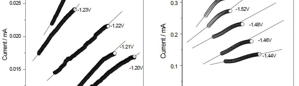
Figure 2 shows the current versus time (I–t) transients recorded during the reduction of the zinc ions, in the potential range from –1.20 V to –1.24 V in absence of VG and –1.44 V to –1.52 V in presence of VG in the plating bath. The behaviour of these current transients is typical of a nucleation process, with three-dimensional (3D) growth of nuclei controlled by the diffusion of the electroactive species. All the curves showed initial sharp rise in short time until the current reaches the maximum value (Imax). This sharp rise in current is probably due to the growth and stabilisation of initial nuclei. The decay in current density after reaching Imax of each transient converges almost to a limiting current and the nucleation process is controlled by the diffusion of zinc ions [9, 18, 14, 23]. The nucleation mechanism is identified by drawing non-dimensional curves and compared with those obtained using the Scharifker and Hills model [23] for three dimensional (3D) instantaneous and progressive nucleation process which are under diffusion control. The model uses the following equation for finding three dimensional (3D) instantaneous and progressive nucleation process.
For instantaneous nucleation <7>,

Equation 7
For Progressive nucleation <8>,

Equation 8
Where I is the current density at any instant of time, Imax is the maximum current density with respect to maximum time (tmax). Hence there are two limiting processes here. Based on equation (7) all nuclei are formed instantly after potential step and is called instantaneous nucleation. Based on equation (8) all the nuclei are formed slowly; their number increases during the entire process and hence it is called progressive nucleation [23].

Fig. 2: Current transients for zinc electrodeposition from
0.55 M ZnSO4 + 0.26 M Na2SO4 + 0.33 M H3BO3 + 0.01 M CTAB, pH = 2.78, Current density = 4 Adm-2, (A) in absence and (B) in presence of 40 mLL-1 of VG
Non-dimensional plots obtained with the experimental and theoretical data for zinc deposition in the absence and presence of VG are shown in Figure 3 at different potentials. Figure 3A shows the nucleation mechanism of zinc deposition in absence of VG. The rising part of the transients is located near the instantaneous nucleation curve. As soon as the potential changes to more negative values, the nucleation process does not confirm to either of the models of the diffusioncontrolled 3D nucleation.

Fig. 3: Non-dimensional (I / Im)2 versus t / tm plot for electrodeposition of zinc coating obtained from 0.55 M ZnSO4 + 0.26 M
Na2SO4 + 0.33 M H3BO3 + 0.01 M CTAB, pH = 2.78, Current density = 4 Adm-2, (A) in absence and (B) in presence of 40 mLL-1 VG
Figure 3B shows the nucleation mechanism of zinc deposition in presence of VG. The rising part of the transients is located on instantaneous nucleation curve. This result confirmed that the nucleation process occurs by instantaneous nucleation in presence of VG.
Another diagnostic characteristic given by Schariffker and Hills nucleation model is based on the rising part of the current-time transient curves, which is based on the early stage deposition analysis [14, 23]. It is possible to plot I versus t1/2 for instantaneous nucleation and I versus t3/2 for progressive nucleation. Figure 4A shows the plot of I versus t1/2 obtained in the absence of VG confirms instantaneous nucleation mechanism, under the given experimental conditions. In Figure 4B, the plot of I versus t1/2 obtained shows similar linearity in presence of VG. Hence this result confirms instantaneous nucleation mode of deposition in bright zinc deposit.

Fig. 4: Dependence between (A) I versus t1/2 plot for initial transient portion of zinc electrodeposit in absence of VG from Fig. 2A and (B) I versus t1/2 plot for initial transient portion of zinc electrodeposit in presence of VG from Fig. 2B
3.4 Corrosion resistance studies
The corrosion resistance studies were done with Electrochemical Impedance Spectroscopy (EIS) and polarisation technique. Figure 5A shows the comparison of Nyquist impedance plot of zinc deposit in absence and presence of VG in the optimized bath. The charge transfer resistance value of the deposit obtained in absence and presence of VG was about 2.9 Ω/cm2 and 864 Ω/cm2 respectively. This result suggests that the bright zinc coat increases the corrosion resistance thereby reducing the corrosion rate of the steel substrate. This is in good agreement with the polarisation results obtained. The Tafel results showed the Icorr value was 0.91 mA/cm2 for dull deposit and 0.79 mA/cm2 for bright deposit. [Fig. 5B]. There is decrease in Icorr value and the deposition potential (Ecorr) value shifts in nobler direction, indicating an increase in corrosion resistance. This result suggests that the bright deposit can successfully act as a protective layer for mild steel substrate and also improve the corrosion resistance of the bright coating.

Fig. 5: (A) Nyquist Impedance plot (B) Tafel polarisation curves of zinc coating in 3.5 wt.% NaCl solution. The zinc electrodeposits obtained a in absence and b in presence of VG
3.5 Surface morphology – SEM Analysis and Reflectance studies
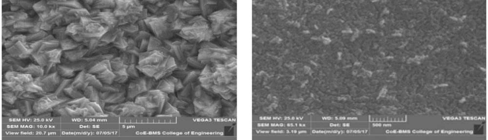
The SEM image [Fig. 6A] shows non-uniform and coarse-grained zinc deposit obtained in absence of VG. The addition of VG increases the formation of fresh nucleation sites during deposition process and decreases the growth of zinc nuclei, resulting in the formation of fine grained deposit [Fig. 6B]. This is in good agreement with the result obtained from XRD analysis. The reflectance and degree of total reflection as a function of wavelength of visible light for zinc coating is shown in Figure 7. It can be seen from the reflectance spectra that the addition of VG into the bath solution leads to an increase in the degree of reflection. Only 3-4 % of variation in total reflectance was observed at different surface points of zinc coating [24]. These results confirmed that VG can be used as a brightener for zinc coating.

Fig. 6: SEM images of zinc electrodeposits at current density 4 A dm-2 (A) in absence and (B) in presence of VG, in the optimized zinc bath solution

Fig. 7: Reflectance spectra of zinc electrodeposition at 4 Adm-2 in (a) absence and (b) presence of VG, obtained from the optimized zinc bath solution
3.6 XRD Analysis
The X-Ray diffraction pattern observed in Figure 8 shows the formation of lines corresponding to η-phase and γ-phase of zinc. All the peaks are corresponding to only zinc metal, indicating that there are no impurities in the electrodeposit.
The diffraction pattern also shows the broadening of the X-ray diffraction peaks in presence of VG, in the bath solution. Broadening of XRD peak usually corresponds to a decrease in zinc crystallite size in the deposit which is also supported by SEM result. From the XRD peaks obtained, the average grain size of zinc crystallites was found to be 75 nm in absence of VG whereas in presence of VG it was found to be 28 nm. These results confirmed the formation of fine grained deposit.
The XRD pattern for the deposit in basic bath, shown in Figure 8a, indicated (002) as the preferred orientation. This infers that in absence of VG, the zinc crystallites prefer (002) orientation [9]. The XRD pattern for the deposit in basic bath with VG is shown in Figure 8b and indicated (110) as the preferred orientation which infers that in presence of VG zinc crystallites prefer (110) orientation. These observed results are in good agreement with the referred data in the literature [25]. This preferred orientation arises due to different growth rates of different faces of the crystal, which in turn is due to the adsorption of VG on the cathode surface [26].

Fig. 8: XRD pattern of zinc electrodeposition observed in (a) absence and (b) presence of VG in the optimized zinc bath solution
The surface modifications like refinement in grain structure and preferred orientation along (110) planes of the zinc deposit was responsible for the smooth and bright appearance of the coating. Hence, these results revealed that bright zinc deposit obtained in presence of VG, was composed of pure zinc phase and was found to be smooth and shiny.
4 Conclusions
- The decorative bright zinc coating was prepared in presence of VG from acid sulphate bath.
- The cyclo voltammetric studies showed that, in presence of VG the reduction peak potential shifts towards more negative direction, which indicates that VG acts as barrier by getting adsorbed on the cathode surface and hence inhibits the deposition rate of metal ions. This inhibition of deposition rate corresponds to the increase in charge transfer resistance and lowering of the deposition rate due to a decrease in exchange current density. The voltammogram also revealed that, on reversing the potential scan in opposite direction, the height of the anodic peak decreased in presence of VG, when compared to its height in absence of VG, corresponding to the decrease in dissolution of zinc from η- and γ-phases.
- The current transient analysis confirms the bright zinc electrodeposition by (3D) three-dimensional instantaneous crystal growth mechanism.
- SEM, XRD and Reflectance analysis reveal the formation of fine grained and bright deposit in presence of VG. XRD studies also depict the presence of η and γ-phases of pure zinc in the deposit.
- VG is also responsible for increasing the corrosion resistance of the zinc deposit since refined grain structure is closely associated with corrosion resistant property. The Corrosion studies done by Electrochemical Impedance Spectroscopy and Tafel polarisation technique prove the increase in corrosion resistance of the bright zinc coating obtained in presence of the newly synthesised brightener (VG).
The proposed studies suggest that the newly synthesized brightener (VG) is efficient in producing bright deposit and can be synthesised by simple method. Hence it can be conveniently used in large scale zinc plating applications.
Acknowledgment: The authors are grateful to the BTLITM and Kuvempu University, Department of Science & Technology, New Delhi, for providing the laboratory facilities to carry out this work.
References
- Nayana K.O, Venkatesha T.V., Synthesis and reactivity in Inorganic, Metal-Organic and Nano-metal chemistry, (2010), v.40, p.170-178.
- Nayana K. O, Prashanth S. Adarakatti and Pandurangappa M, Ind. Eng chem.Res., (2017), v.56, p. 5284-5295
- F. Ebrahimi, D. Kong, T.E. Matthews Q. Zhai. in processing and fabrication of Advanced Materials by Srivatsan and Khor, TMS Publication, Warrendale, PA, (1998), v. 7th Edition, p.509-521.
- F. Ebrahimi, H. Q Li, Rev. Adv.Mater. Sci., (2003), v.5, p.134-138
- F. Ebrahimi, G.R. Bourne, M.S. Kelley, T.E. Matthews, Nanostructured materials, (1999), v.11, p. 343-350.
- KL Morgan, Z. Ahmed, F Ebrahimi, MRS Proceeding (2001), v.634, B.3.11.1
- F. Ebrahimi, Z. Ahmed, Materials characterisation, (2003), v.49, p. 373-379.
- A.M. Ei Sherrik, U. Erb, Mater Sci. Eng., (1995), v. 30, p.5743-5749.
- Nayana K. O, T. V Venkatesha, B.M. Praveen, Vathsala K. J. Appl. Electrochem, (2011) v.41, p.39-49
- Kim S. J., Kim H.T., Parka S. M. J. Electrochem Soc. (2004), v. 151, NO12, p. C850
- Kavitha B., Santhosh P., Renukadevi M., Kalpana A., Shakkthivel P., Vasudevan T., Surf & coat. Technol. (2006), v.201, p. 3438
- Muralidhara H.B, Arthoba Nayaka Y., Venkatesha T.V., Bull Mater Sci (2006), v. 29 NO 5, p. 497- 503
- Chen D, Martel A.E. Inorg chem. (1987), v. 26, p.1026-1030
- Basavanna S. and Y. Arthoba Nayaka., Study of the effect of new brightener on Zn-Ni alloy electrodeposition from acid sulphate bath, (2011), J. Appl Electrochem, v. 41, p.535-541
- Cullity B D, Elements of X-ray Diffraction, (1978) 2nd Edition, Addision Wesley Publishing company, Inc., Phillipines.
- Berube L.P, Esperance G. L, J. Electrochem. Soc. (1989) v.136, p. 2314-2328
- Basavanna S., Y.A Nayaka, Indian Journal of Chemical Technology, (2012), v. 19, p. 91-95
- Ballesteros J.C., Diaz- Arista P., Meas Y., Ortega R., Trejo G. Electrochim Acta, (2007) v. 52, p.3686
- Zhang Z., Trans Non-ferr Met Soc. China, (2001) v. 11, NO 4, p. 603
- Nayana K. O, T.V. Venkatesha, Effect of ethyl vanillin on Zn-Ni alloy electrodeposition and its properties, Bull. Material Sc mi., (2014), v.37, NO 5, p.1137-1146
- Trejo G., Ruiz H., Ortego Borges R. and Meas Y., Influence of Polyethoxylated additive on zinc electrodeposition from acidic solution, J. Appl Electrochem, (2001), v. 31, p. 685-689
- Serdar A., and Fiona M. D, J. Electrochem. Soc., (2001), v.14, p. 8851
- Schariffker B.R., Hills G., Electrochim Acta, (1983), v.28, p.879
- Basavanna, S., and Arthoba, N. Y., Electrochemical studies of Zn-Ni alloy coatings from acid chloride bath, J. Appl. Electrochem, (2009), v.39, p.1975
- Hsieh J.C, Hu C. C, Le T.C., J. Electrochem. Soc., (2008), v.155, p. D675
- Reddy A. K. N., J. Electroanal Chem, (1963), v.6, p. 141
PDF Version of the article |
Flash Version of the article |
|
| [qrcode] | ||