
 Fig. 2: Early red corrosion of ZnNi plated parts after 192 h NSST Parts are black passivates and sealed with an organic sealer. ZnNi layer contains > 16 % Ni
Electrodeposited zinc-nickel coatings are broadly used as sacrificial coatings for steel since many years in the automotive industry and for other high corrosion resistant applications. The best corrosion resistance is obtained with ZnNi deposits having 12–15 % Ni in the alloy. Many studies were performed showing the influence of nickel content in the alloy [1]. In industrial plating electrolytes other metals than Zn and Ni can be present. In alkaline zinc-nickel electrolytes mild steel is usually used as anode material. Depending on electrolyte composition and plating conditions more or less iron can be dissolved by anodic dissolution into the electrolyte. It is well known that the iron is codeposited into the zinc nickel alloy, but the effect on the alloy properties was never systematically investigated. In this study the influence of up to 800 mg/L iron in commercially used alkaline zinc nickel processes is investigated. Up to 8 % iron is amorphously codeposited in the alloy. No new iron containing phases could be detected by X-ray diffraction (XRD). ZnNi g-phases (Ni2Zn11/Ni5Zn21) are still the dominant phases, but plain orientation can be affected by iron codeposition. Corrosion properties are investigated by electrochemical measurements and neutral salt spray test. Whereas no huge difference in the corrosion properties between the bare ZnNi and ZnNiFe coatings was observed, the corrosion resistance with a subsequent trivalent chromium passivate can be drastically improved using iron in the alloy.
1. Introduction
In the beginning of the industrial applications of zinc-nickel coatings in the 1970s mainly low alloyed ZnNi processes with approx. 8–10 % Ni were on the market. In the 1980s first high alloyed system with 12–15 % Ni were developed and began to gain market share throughout the 1990s. Today, high alloy systems have more or less completely replaced the low alloyed technology because of the much improved corrosion resistance. Despite of the discussion around the health risks of using nickel compounds zinc-nickel processes are still gaining market share replacing zinc coatings to increase corrosion resistance and are also seen as a good candidate to replace cadmium coatings which are still used e. g. in the aerospace industry. The excellent corrosion properties of the zinc-nickel processes with 12–15 % nickel are related to the deposition of the ZnNi g-phases (Ni2Zn11/Ni5Zn21) which is the thermodynamically preferred phase between 14 and 25 wt% nickel as can be seen in the ZnNi phase diagram (Fig. 1).
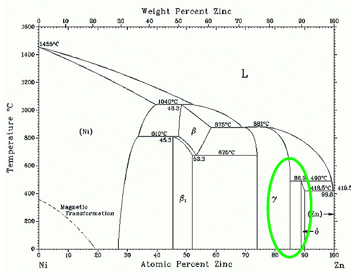
Fig. 1: ZnNi phase diagram Source: Landolt-Börnstein, Binary Systems part 5: Supplement 1, Volume 19 Thermodynamic Properties of Inorganic Materials Group IV Physical Chemsistry
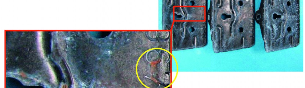
Nevertheless the Ni content should not exceed 16 % nickel to maintain the corrosion potential anodic compared to the steel substrate. Otherwise the substrate would no longer be cathodically protected. In such cases early red corrosion (substrate corrosion) can be observed e.g. in the neutral salt spray test (see Fig. 2).
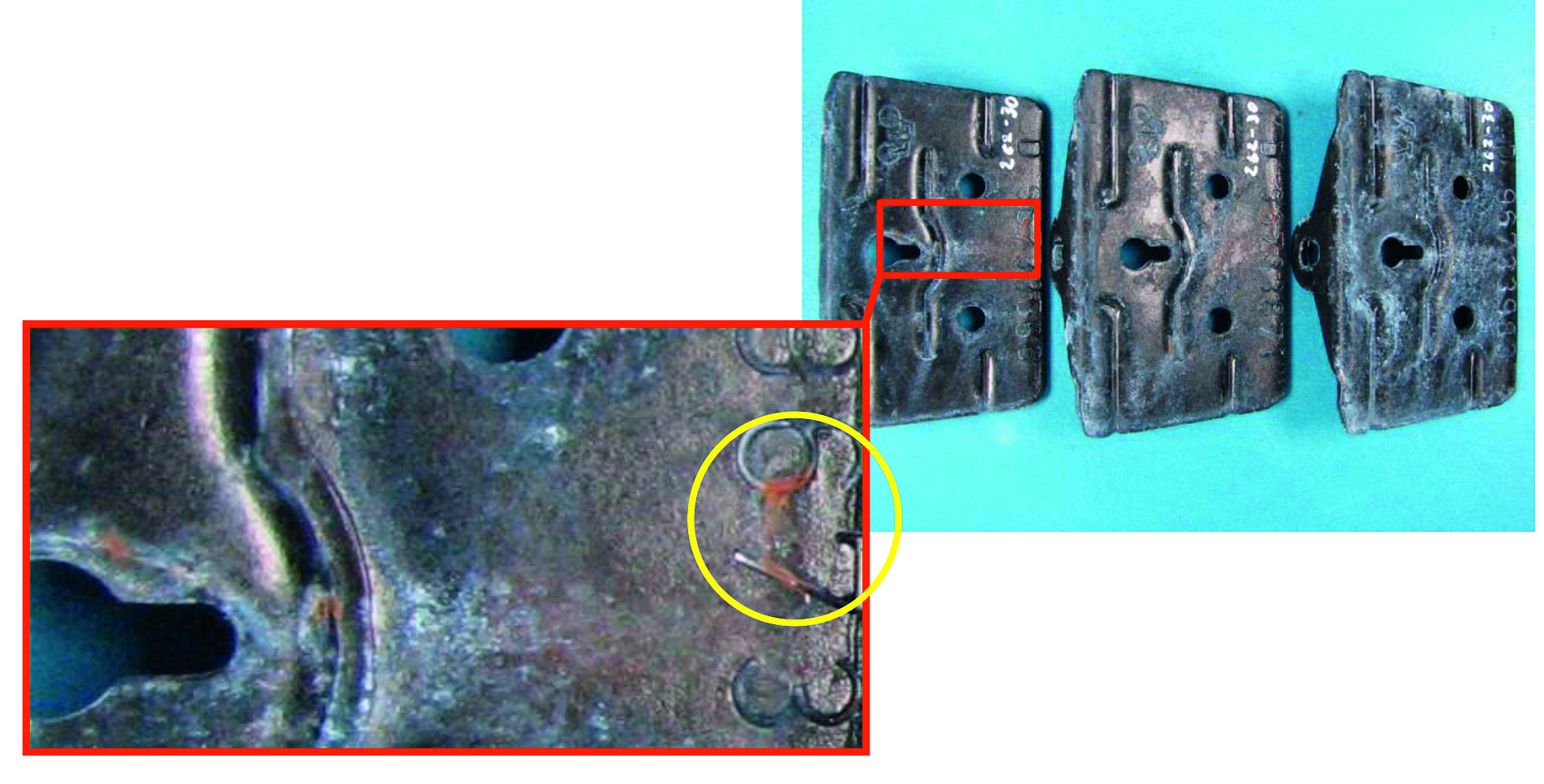
Fig. 2: Early red corrosion of ZnNi plated parts after 192 h NSST Parts are black passivates and sealed with an organic sealer. ZnNi layer contains > 16 % Ni
That means a quite narrow alloy composition range of 12–15 % Ni has to be maintained over a broad current density range. That is a challenging task both for the developer of the ZnNi process chemistry and for the applicator in the plating shop. And of course the question arises what happens if the ZnNi composition is out of range or if further metals e. g. from impurities in the bath are codeposited in the ZnNi alloy? Especially iron is an element that is often found in industrial ZnNi electrolytes by anodic dissolution of steel anodes or by drag-in from pre-treatment steps. It is known that too much iron may lead to insufficient throwing power and dark aspect in low current density areas [1]. The effect of iron on the corrosion resistance is still not well understood. Sometimes a decreased corrosion resistance is reported even with impurities of 50 mg/L Fe or lower. On the other hand we never saw an effect on the corrosion resistance in industrial applications with 100 mg/L Fe or more. In the scientific literature about Zn-Ni-Fe alloys only studies with acidic electrolytes can be found [2, 3, 4, 5, 6]. It is reported that iron is codeposited in form of Fe3Ni2 phases [4]. It was found that iron acts as brightener [4] and improves corrosion resistance [4, 5]. By far the most industrial electrolytes are alkaline amine based systems and it is questionable if findings for acidic electrolytes can be applied to alkaline systems. In this work the influence of iron in two commercially available zinc-nickel electrolytes (Performa 285 and Performa 288 from Coventya) are investigated.
Experimental procedure
The zinc nickel electrolytes were prepared with the following parameters:
Performa 285
| NaOH 130 g/L | |
| Zn 9 g/L | (by adding Zincate Solution) |
| Ni 0.9 g/L | (by adding Performa 285 NI-CPL, contains nickel sulfate and amines) |
| Performa 285 Base | 100 mL/L (mixture of amines) |
| Performa 285 BRI UNI | 1 mL/L (brightener) |
Performa 288
| NaOH 120 g/L | |
| Zn 9 g/L | (by adding Zincate Solution) |
| Ni 1.3 g/L | (by adding Performa 288 NI-CPL, contains nickel sulfate and amines) |
| Performa 288 Base | 160 mL/L (mixture of amines) |
| Performa 288 BRI MU | 1.5 mL/L (brightener) |
Dl water is used for all electrolytes. Iron is added as iron(III) sulfate.
ZnNi plating procedure
Hull cell panels: The copper panels are cleaned with a mild alkaline cleaner and activated in mild acidic solution. The panel is plated with 2 A for 30 min at 23 °C in a tank with standard Hull cell geometry, but with an extra electrolyte reservoir (1 L) to ensure constant concentrations of electrolyte constituents during plating.
Rack plating: The parts are cleaned with soak cleaner and deoxidized with a hydrochloric acid pickling followed by an alkaline electrolytic cleaner and an acidic activation. The parts are plated in a 50 L tank with rack movement with 2 A/dm2 for 40 min at 23 °C.
Trivalent chromium passivation
Rack parts are passivates with commercially available cobalt-free passivates:
- Finidip 728.3 (black passivate, 80 mL/L Part A 70 mL/L Part B, pH 1.9, 25 °C, 60 s)
- Finidip 128 CF (transparent passivate, 160 mL/L, pH 2.6, 25 °C, 60 s)
X-Ray fluorescence measurements
X-ray fluorescence (XRF) measurements to determine coating thickness and alloy composition were performed on a Fischerscope® X-Ray XDV®-SDD.
X-Ray diffraction measurements
X-ray diffraction (XRD) measurements were performed on a Bruker D8 Advance diffractometer using a CuKα radiation with wavelength of λ 0.15406 nm produced at 40 kV and 40 mA. XRD data were collected over the 2θ range from 20° to 100° at every 0.02° for the scan speed of 0.5 s per step. The crystalline phase was identified by reference to the Joint Committee on Powder Diffraction Standards (JCPDS). All measurements were performed at the Institut Utinam, Université de Franche-Comté.
2. Results and discussion
Aspect
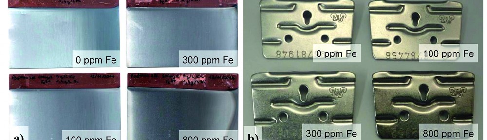
The Influence of iron addition on the aspect of ZnNi deposits plated with Performa 288 can be seen in Figure 3. Higher iron content leads to darker appearance on the pictures, which is mainly caused by a higher brightness, means iron works as a grain refiner. It can be also seen in Figure 3a that too much iron leads to a dark aspect in the low current density at the right corner of the Hull cell panel. A very similar behaviour can be observed in the second investigated ZnNi electrolyte Performa 285 (not shown here).
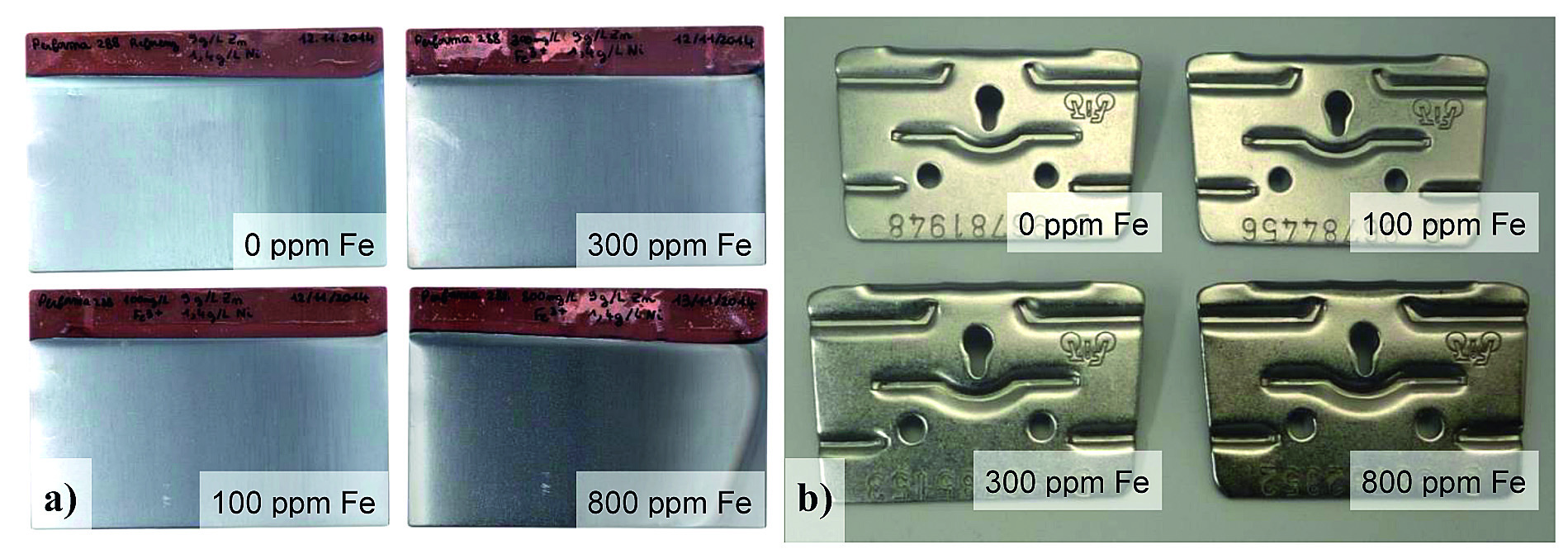
Fig. 3: Influence of iron addition on the aspect of Performa 288 ZnNi coatings, a) Hull cell panels plated with 2A for 30 min, b) Rack parts plated in a 50 L pilot line tank with 2 A/dm2 for 40 min
Alloy composition
It is interesting to note that the iron codeposition can have different effects on the current efficiency. Depending on the amine mixture used for complexing the nickel, the current efficiency is reduced esp. in the high current density (for Performa 285) or more or less unchanged (Performa 288, see Fig. 4).
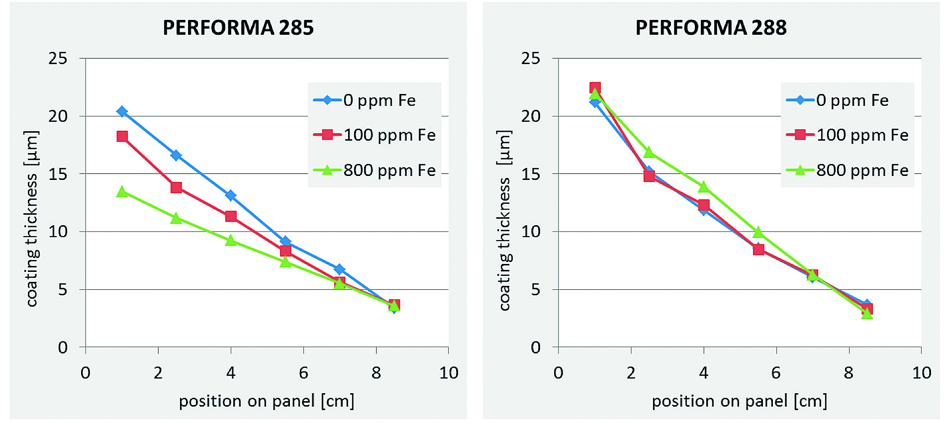
Fig. 4: Influence of iron addition on the ZnNi coating thickness on Hull cell panels plated with 2 A for 30 min
The different codeposition rates of Fe into the ZnNi alloy are also related to the complexing agents in the electrolytes (see Fig. 5). As expected the Ni codeposition is reduced with increasing Fe content keeping the ratio Zn to Ni more or less constant.
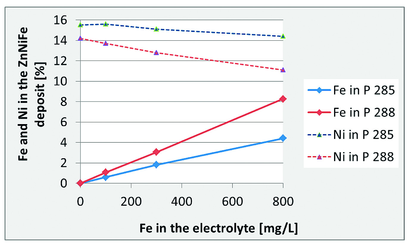
Fig. 5: Iron codeposition from two different ZnNi electrolytes (Performa 285 and Performa 288) with iron contamination
Crystal structure
It is well known from previous internal studies and publications [1, 2] that the plane orientation of the ZnNi g-phase crystals is important for the physical layer properties. The bendability of ZnNi deposits plated in the (330) plane orientation is better than the bendability of (600) deposits. The preferred plane orientation is one major difference between the process Performa 285 and Performa 288 (see Fig. 6). The better bendable (330) processes are preferred for rack application esp. for parts that have to be bended after plating. In Figure 6 it can be seen that too much iron in the deposit can change the preferred plane orientation from (330) to (600), which means that the bedability of deposits is probably worse.
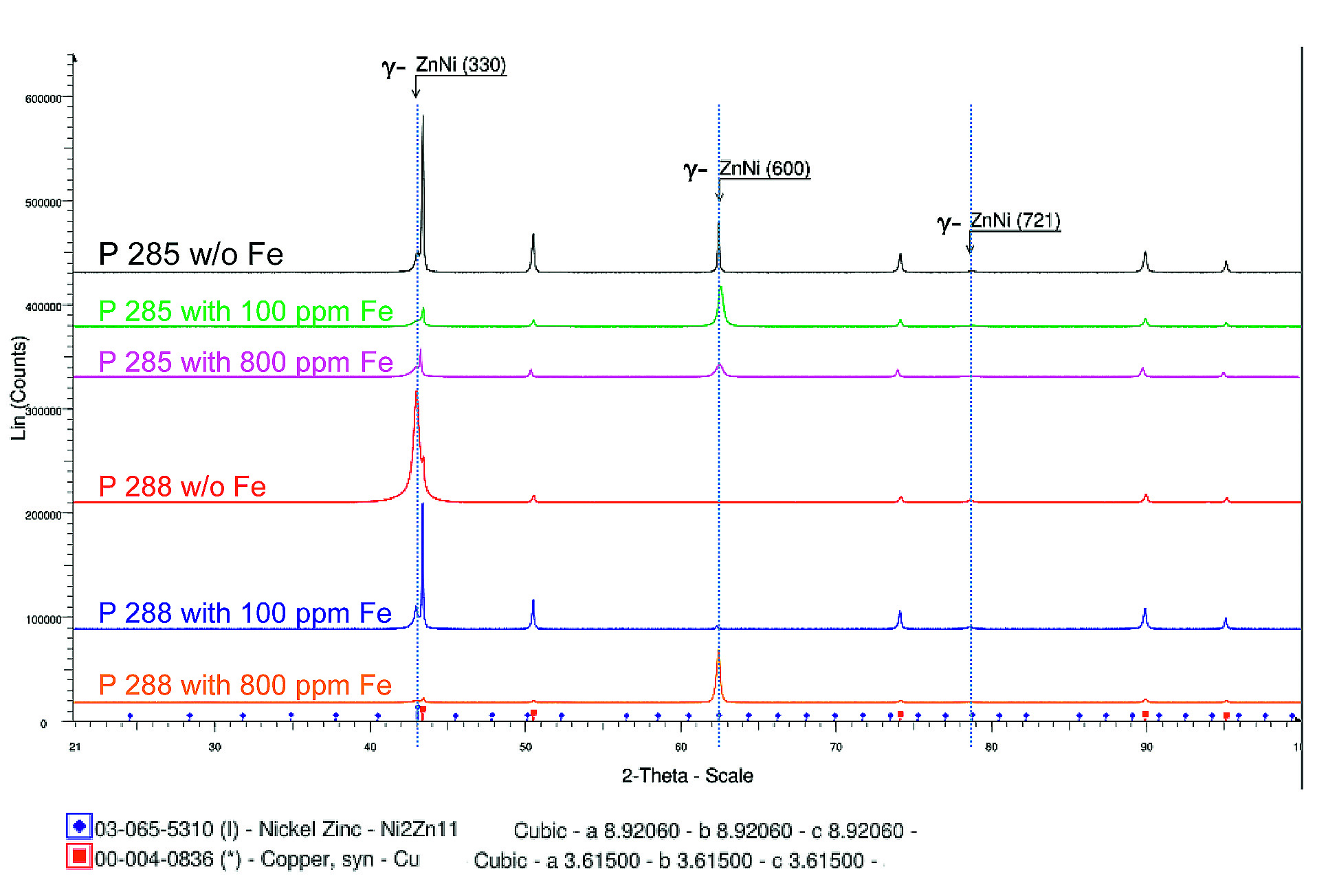
Fig. 6: Influence of iron codeposition on the XRD pattern of ZnNi coatings plated on copper substrates at 4 A/dm2
But this has not yet been tested. It can be expected that also the iron codeposition itself may have an effect on the mechanical properties including bendability. From the XRD data it can be furthermore concluded that Fe is amorphously codeposited into the ZnNi matrix. No new signals related to FeZn, FeNi or ZnNiFe phases can be observed and ZnNi still appears as g-phase which is important to maintain the good corrosion properties. This XRD investigation has been performed on copper panels plated with two different current densities (4 and 0.5 A/dm2). In both cases results are identical.
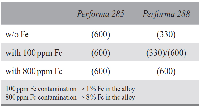
Table 1: Plane orientation of g-phase ZnNi crystals
Corrosion properties
The most important property that is attributed to ZnNi coating is the corrosion resistance which is much higher than the resistance of pure zinc coatings under most climatic conditions. This is related to the lower potential difference between the coating and the steel substrate (see Fig. 7) and to kinetic effects that hinder the progress of the corrosion of ZnNi layers by their own corrosion products.
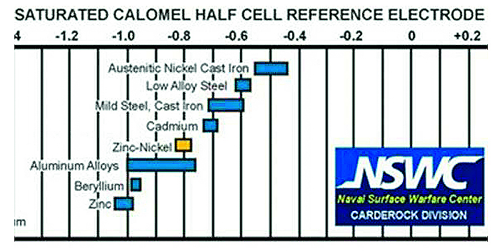
Fig. 7: Corrosion potentials, measured in flowing sea water, Source: Naval Surface Warefare Center
Electrochemical measurements:
It can be expected that the addition of iron to the alloy will further shift the corrosion potential of the ZnNiFe alloy to the cathodic direction closer to the potential of the steel substrate. This was proved by electrochemical measurements (Fig. 8).
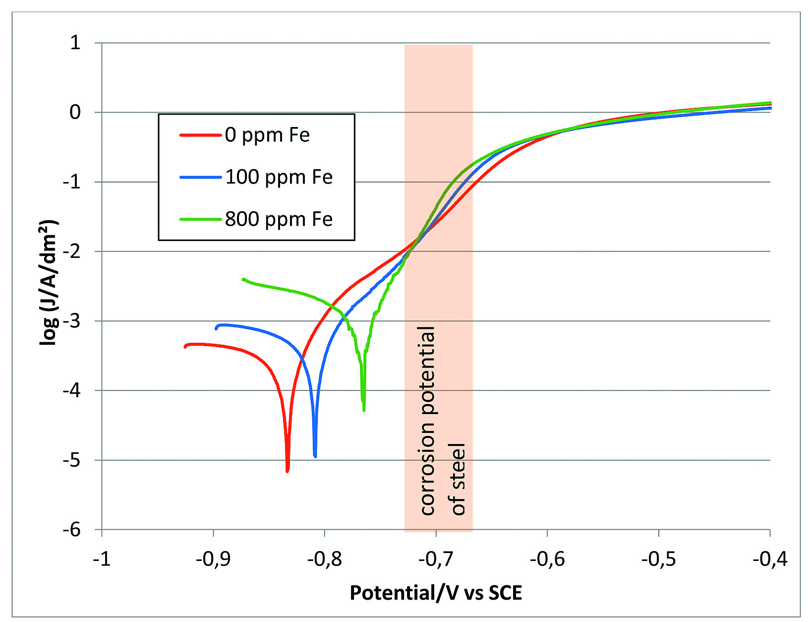
Fig. 8: Influence of iron codeposition on corrosion potential of ZnNi alloys. Electrolyte:
5 % NaCl, pH 6.5, sweep rate: 0.1 mV/s, reference: SCE (measurements from TU Ilmenau)
100 ppm Fe contamination → 1 % Fe in the alloy
800 ppm Fe contamination → 8 % Fe in the alloy
A more cathodic corrosion potential means that the alloy is thermodynamically more stable and a better corrosion resistance can be expected. However this is not true here, because corrosion kinetics seemed to be influenced by the incorporated iron. The corrosion current derived from the tafel plots in Figure 8 increases with increasing iron content (see Table 2).
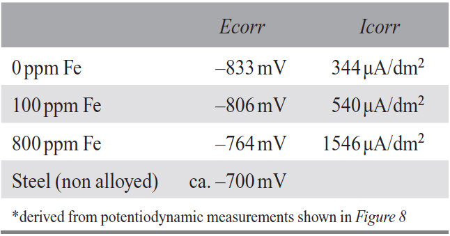
Table 2: Corrosion potentials (Ecorr) and corrosion currents (Icorr)*
Neutral salt spray test
The corrosion resistance of ZnNi plated parts with and without iron contamination is tested in neutral salt spray test (NSST) according to EN ISO 9227. Since ZnNi coatings are never used blank without subsequent passivation, two different cobalt-free trivalent chromium passivates were applied, a transparent passivate (Finidip 128 CF) and a black passivate (Finidip 728.3). The results after 408 h NSST are shown in Figure 9.
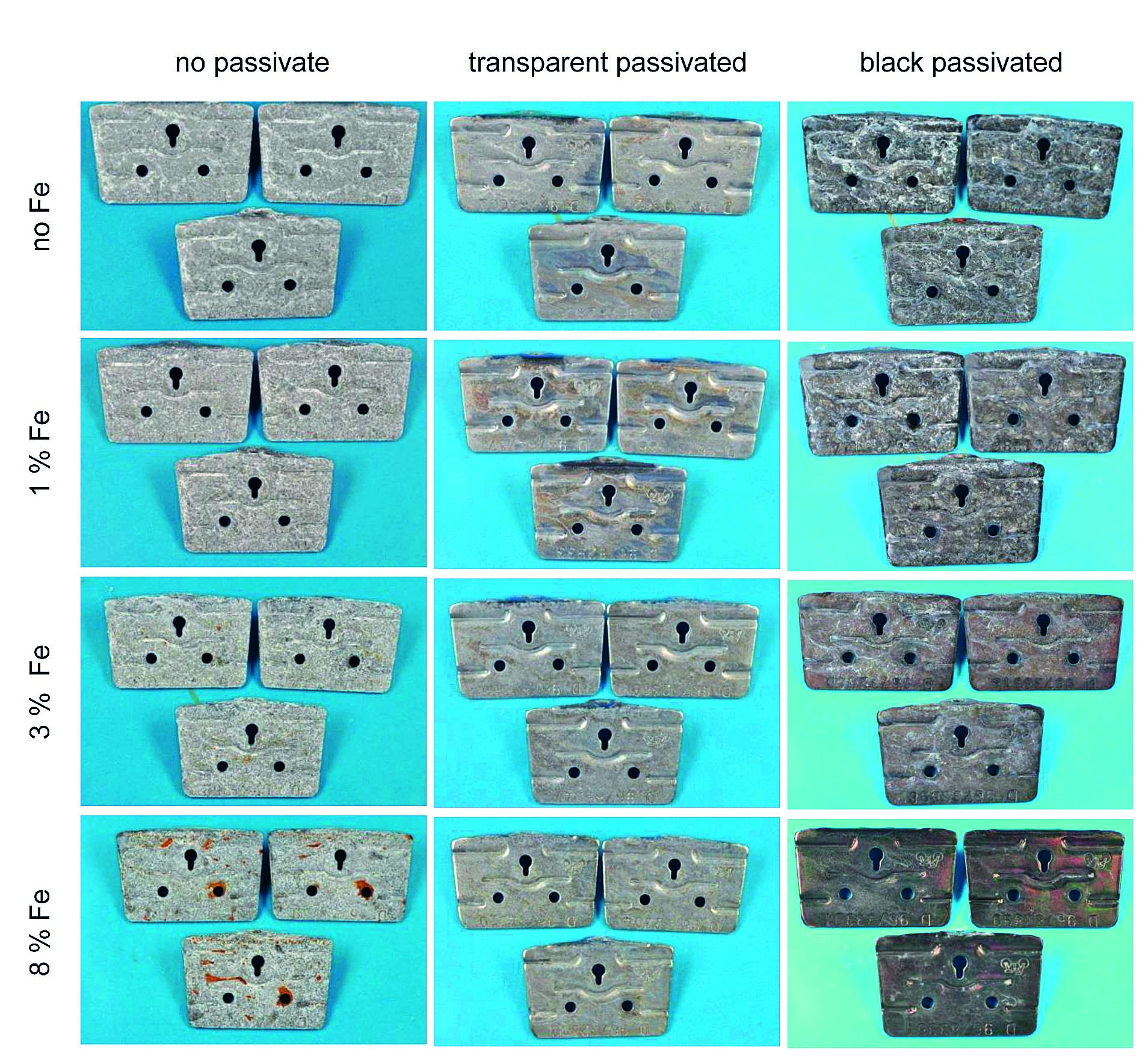
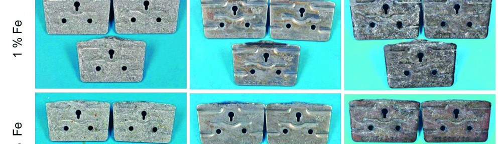
Fig. 9: Corrosion results after 408 h NSST for ZnNi(Fe) plated parts with different passivates
100 ppm Fe contamination → 1 % Fe in the alloy
300 ppm Fe contamination → 3 % Fe in the alloy
800 ppm Fe contamination → 8 % Fe in the alloy
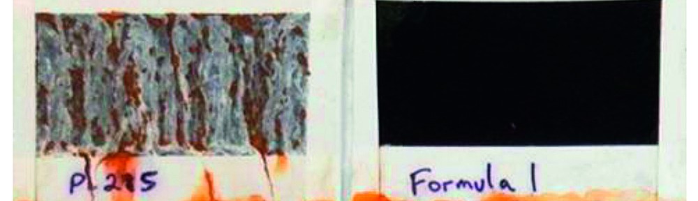
The non-passivated parts show white (zinc) corrosion already after a few hours. This aspect is more or less unchanged during the whole corrosion test. This is true for ZnNi coatings without and with up to 3 % Fe. With 8 % Fe the iron from the ZnNiFe alloy (not the substrate) starts to corrode leaving red corrosion products on the parts as can be seen on the bottom left picture in Figure 9. Comparing the corrosion pictures of the transparent passivated parts no significant differences can be seen, whereas a huge effect of the iron codeposition on the corrosion of the black passivated parts can be observed. It is well known that black passivated ZnNi coatings tend to form early white corrosion, often named as “white haze” which appears usually already after 24 h NSST. This effect can be minimized by applying an organic top-coat or a chromium phosphate based post-dip. With addition of 800 ppm iron into the electrolyte this white haze can be completely prevented, even after 408 h NSST (see right column in Figure 9, so that no further post-treatment is necessary. This can be very interesting for applications where no post-treatment can be used for e. g. for connectors where a post-treatment would increase the electrical resistance to a non-acceptable level. This surprising effect of Fe on the corrosion properties of black ZnNi deposits is used for a current product development of a dedicated ZnNiFe coating in combination with a special black passivate which gives deep black aspect with low electrical resistance even after NSST. A patent is pending for this technology. In Figure 10, the latest status of the development can be seen. The passivate is optimized for the ZnNiFe alloy and leads to early red corrosion of conventional ZnNi coatings containing 15 % Ni.
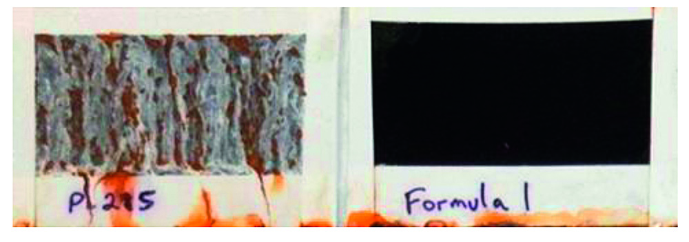
Fig. 10: Comparison between conventional ZnNi coating (left) and the new developed
ZnNiFe coating (right), both passivated with a special chromium(III) based black passivate
after 312 h NSST
3. Conclusion
This study shows that iron in concentrations up to 100 mg/L in the electrolyte does not have significant effects on the properties of ZnNi coatings. Higher concentrations with 300 mg/L or more may influence the crystal structure and the bendability of the deposits. The effect of iron in the different industrial ZnNi processes can be different and depends mainly on the complex chemistry of the electrolyte formulation. Surprisingly it was found that codeposition of iron can prevent the appearance of early white corrosion of black passivated ZnNi deposits in neutral salt spray test. The development of ternary ZnNiFe alloys together with dedicated passivates has the potential to open new types of application for zinc alloy coatings. However it has to be mentioned that this system is still in an early development phase and several important properties, e. g. behaviour in cyclic corrosion tests and corrosion under natural exposure conditions are still not investigated but will be part of the future work on this research project.
Acknowledgment
The author thanks the coworkers of the Coventya R&D workgroup in Guetersloh, Germany, particularly Markus Jahn and Noémie Mazué (student from DUT Besançon, Frankreich) who performed the study. Thanks to Tony Oriti from Coventya Cleveland, USA for the research study on the black passivated ZnNiFe alloys.
References
- T. Murai: Performance Characteristics of Zinc-Nickel Alloys and Dip- Spin Coatings, metalfinishing.com
- Unpublished results from Coventya
- V. Raghavan: Fe-Ni-Zn (Iron-Nickel-Zinc), J. Phase Equilib. 24 (2003)
- M.M. Abou-Krisha: Electrodeposition behavior of zinc-nickel-iron alloys from sulfate bath, J. Coat. Technol. Res. 6 (2009)
- A.C. Hedge: Electrodeposition of Zn–Ni, Zn–Fe and Zn–Ni–Fe alloys, Surf. Coat. Technol. 205 (2010)
- M.M. Abou-Krisha: The influence of Fe2+ concentration and deposition time on the corrosion resistance of the electrodeposited zinc– nickel–iron alloys, Arabian J. Chem. (2012)
- M.M. Abou-Krisha: Effect of pH and current density on the electrodeposition of Zn-Ni-Fe alloys from a sulfate bath, J. Coat. Technol. Res. 9 (2012)
- T. Oriti: A Comparative Study of Gamma-Phase Zinc-Nickel Deposits Electroplated from Various Alkaline and Acid Systems, NASF Surface Technology White Papers 79 (2014)
- C.V. Bishop: Gamma Phase Zinc Nickel Electrodeposits from Alkaline Electrolyte, SAE Technical Papers (2005)
PDF Version of the article |
||
| [qrcode] | ||