
In Part 1 of this series on the electroless deposition of palladium, the properties of the metal itself were discussed as well as the benefits of the electroless deposition process. In Part 2, the autocatalytic position processes are detailed with an exhaustive review of previously published work in this area.
Link: Electroless Deposition of Palladium – Part 1
3. Electroless autocatalytic metaldeposition processes
Reducing agents employed for electroless deposition include hypophosphite (usually as NaH2PO2), hydrazine hydrate (N2H4.H2O), sodium borohydride (NaBH4), dimethylamino-borane (trivially DMAB), [(CH3)2NH:BH3], and tertiary amine boranes. Formaldehyde (HCHO) is used as a reducing agent in substantial quantities, but almost exclusively for copper deposition on PCBs and allied circuitry. Reasons for choosing one reducing agent over another may include; whether it works in a preferred pH range, or even at all; the physical properties of resulting deposits; if the presence of c0-deposited elements, especially phosphorus (from hypophosphite) or boron (from boranes or borohydride) is desirable or undesirable. Many readers will already be aware that in the case of electroless nickel deposits, co-deposited phosphorus or boron modifies the physical and chemical properties of nickel substantially.
Burelli [18] reviewed the thermodynamic & kinetic aspects of electroless plating, noting that Pd is the most powerful catalyst of the group Pd, Pt, Ag and Au. Because the precious metals are strongly electropositive, they require relatively more powerful reducing agents; those more often used for Pd are hypophosphite or hydrazine. Burelli gives the following potentials for palladium vs. reducing agent at pH 7 assuming only simple ions and 1 molar concentration:
– Pd – H2PO2– 1.5 V
– Pd – BH4¯1.5 V
– Pd – N2H4¯ 2 V
3.1. Investigations by Rhoda
The first autocatalytic electroless palladium processes appear to be those reported by Rhoda [19]; the process solutions he employed contain tetrammine palladium(II)chloride [Pd(NH3)4Cl2] together with NH4OH, hydrazine, and EDTA disodium salt, as shown in Table 4.
![Tab. 4: Electroless palladium, process solutions and parameters (reported by Rhoda [19])](https://www.jept.de/wp-content/uploads/2015/05/tab-41.png)
Tab. 4: Electroless palladium, process solutions and parameters (reported by Rhoda [19])
Comments on functions
Palladium is present as the soluble amine complex [Pd(NH3)4Cl2], which supplies Pd++ ions to be reduced by N2H4 to Pd0. A substantial excess of an amine, ammonium hydroxide being the most usual, is needed to maintain solubility of the Pd complex and, in conjunction with a stabiliser, ensure that Pd++ ions are released at a rate compatible with the reducer content (common ion effect).
Stabiliser attempts to increase deposition rate by raising temperature and concentrations, cause spontaneous decomposition or “seeding”, unless a stabiliser is present. EDTA was found to be best and is compatible with amines, of course. The writer suggests the benefit from EDTA noted by Rhoda might well be due in part to complexation of low level contaminants disregarded in 1960s (such as Fe in NH4OH). Note that tetrammine palladium dichloride was prepared by Rhoda by dissolving the diammine [Pd(NH3)2Cl2] in NH4OH to produce the pale yellow complex [Pd(NH3)4Cl2] required. Alternatively, he suggested adding NH4OH to palladous chloride solution and heating to dissolve the precipitate so formed. All these Pd complexes are today readily available from specialist firms such as Heraeus, Johnson Matthey, Metakem, Metalor, Umicore.
Hydrazine: this is a powerful reducing agent and must be added as a dilute solution, just before plating is to commence. If any hydrazine remains after completion of a job and removal of work-pieces from the bath, the reaction N2H4 + Pd++ Pd0 may continueto exhaustion if any catalytic material is present (e. g. metallic dusts). Reducing agents are relatively expensive bath components, other than the PGMs of course; the question of economic operation of electroless Pd baths is to be considered later, and is the subject matter in Keuler et al [16].
pH: Rhoda made no reference in this paper to pH value or control; with an ammonium hydroxide content ca. 300 g/l, and hence a pH perhaps 9 to 10, he might well have thought this was unnecessary. Additionally, glass pH electrodes available in the 1960s were much more fragile than nowadays and usually unreliable above pH 8 to 9.
Barrel plating; this was done in an “oblique barrel” mounted with the major axis at say 45°, as distinct from a perforated cylinder immersed in process solution.
Deposit properties
Visual / ductile, adherent, grey to white, does not blistering when heated
Hardness range / 150 to 350, mean 257 KHN25 (i. e. Knoop hardness number at 25 g load)
Purity / > 99.4 % Pd; density 11.96 g/cm3; lattice parameter 3.8865 Å
This high purity of deposit is to be expected with a totally labile reducing agent, such as N2H4.
A later paper by Rhoda [20] is a more detailed account of the barrel plating portion of his earlier work paraphrased above (see [19]), with details of substrates plated and deposition rates achieved. The optimum solution composition varied slightly from Table 2, being:
Pd / 2.5–20 g/l
EDTA / 8 g/l
NH4OH / 250 g/l
Temperature / 25–45 °C
Work loading / 0.56 dm2 (100 connectors)in 0.7 litres
Hydrazine add’n. / 4–24 mls of 1 M(ca. 0.1–0.8 g N2H4) per hour
The maximum plating thickness obtained was 2.5 µm in 1¾ hours, operating at 45 °C, Pd 10 g/l, and adding 1M hydrazine at 8 mls per 15 minutes.
An unusual observation was that when regular aliquots of hydrazine (based on a predetermined rate of consumption), were added during an extended plating run, the ratio of excess N2H4 to Pd ions increased, and it was found necessary to ramp down additions as otherwise this build-up led to premature bath decomposition. Conversely, as Rhoda described in [19], during rack plating it was found that plating rate fell with time as hydrazine was depleted, probably due to catalytic decomposition by metallic Pd previously deposited. This latter case is the general experience with e. g. electroless nickels, probably due to plating out onto to any metallic contamination and interference from sodium phosphite or other reaction products.
In 1962 Rhoda [21] published a paper on depositing electroless Pd directly on to Ge and Si. In particular he envisaged using electroless deposits of Pd as barrier layers between gold and nickel in electronic devices, to prevent inter-diffusion of Au & Ni in electronics generally. His prevision of the ENEPIG process (discussed later) is certainly striking.
3.2. Investigations by Pearlstein & Weightman
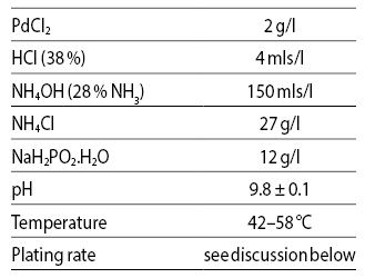
Pearlstein & Weightman [22] reported an electroless Pd solution employing hypophosphite as reducing agent. Pd is present as a palladous ammine complex, prepared by slowly adding a solution of 20 g/l PdCl2 dissolved in 40 mls/l concentrated HCl (38 %) and diluted to 1 litre, to the appropriate volume of NH4OH (28 %); the resulting solution is aged at ambient for 24 hours and then filtered. Ammonium chloride is added as stabiliser, the pH adjusted if needed, and finally sodium hypophosphite added. The recommended bath is shown in Table 5.

Tab. 5: Hypophosphite Bath for Pd
(Pearlstein & Weightman)
The deposits were stated to contain about 1.5 % P, and the hardness about 165 kg/mm2. Plating rate increases with temperature and hypophosphite concentration up to about 60 °C and 20 g/l respectively, beyond which the bath becomes unstable.
The proportion of hypophosphite used to deposit Pd is given as ca. 31 % (2.67 g per g Pd) by Okinaka & Wolowodiuk [23], the balance decomposing to release H2 within the solution. In discussing this same process, Ohno states [24] that about 3 g of sodium hypophosphite monohydrate is used per gram Pd deposit, citing Pearlstein in the 1974 edition of Modern Electroplating. The discrepancy is due to the lower figure being calculated as anhydrous sodium hypophosphite.
3.3. Investigations by Ocken et al
An application study using the Pearlstein & Weightman electroless Pd bath is given by Ocken et al [25]. The requirement was to reduce accumulation of 60Co radio-isotope in the passive films formed on type 304 austenitic stainless steel at 280 ºC in the primary coolant circuits of nuclear reactors. Type 304 stainless steel composition is nominally Cr 18 to 20 %, Ni 8 to 12 %, C max. 0.08 %.
(The writer had assumed that welded construction would be used, and so expected grade 304L with a lower content of C max. 0.03 % to be preferred for this application, in view of its much reduced sensitivity to carbide precipitation in welded areas, and thus to intergranular corrosion; however, this aspect was not mentioned.)
The authors employed electroless Pd solution exactly as in Table 4, operating as described in [22]. Test pieces were subjected to a solvent soak for 15 to 20 minutes (in toluene [26]) and anodic hot alkaline cleaning, followed by activation in 25 to 50 % H2SO4 at 70 to 80 °C for 30 to 75 seconds; a brief rinse in distilled water and rapid transfer to the Pd bath followed. Initiation of plating was indicated by gassing immediately after immersion. Plating times of 30 minutes were used in most cases, depositing about 1 µm Pd (Pearlstein & Weightman, op.cit.).
Deposits obtained by this procedure were adherent, with a uniform base layer (i. e. initial Pd deposit) on irregular surfaces, to at least 0.6 µm thickness. Once this base layer has formed, a rough nodular outer layer develops; stirring the solution to increase mass transport and hence plating rate, produced substantial cracking in all areas.
The writer speculates that both nodulation and cracking may be initiated by unattached Pd0 nano-particles formed by the auto-catalytic reduction adjacent to, but not immediately becoming fixed to, the work-piece. Unlike orthodox electroplating, there is no electrical field to encourage ad-atoms in joining the crystal lattice in an orderly manner. Additionally, the authors indicate that cracks visible in surface SEMs are probably not created by deposit stress, but crevices in the substrate due to excessive etching of grain boundaries; electroless Pd deposit thickness and mode of deposition does not, it seems, fill or bridge in the manner of electrodeposition.
Test exposure of plated specimens in service conditions confirmed a substantial benefit in reduction of 60Co uptake in surface film, when a Pd deposit was applied.
3.4. Investigations by Athavale & Totlani
Athavale & Totlani [27] having concluded that the hydrazine-reduced processes reported by Rhoda (op.cit.) were too unstable and inefficient in utilisation of materials to be attractive, undertook a study of the Pearlstein & Weightman process (op.cit.) which uses hypophosphite as reducing agent because it offered better stability and coating quality. They examined the effects of varying the parameters – each bath component in turn, and temperature – on Pd deposition rate, and arrived at an optimum process for smooth, bright, blister-free crystalline deposits, which do not fingerprint. The deposits contain 1.52 to 1.73 % P, and the microhardness 173 VHN at 25 g load.
The process is very close to Pearlstein & Weightman, as can be seen in Table 6.
Tab. 6: Hypophosphite bath for electroless Pd
(Athavale & Totlani)
Athavale & Totlani‘s Figures 1 to 5, show deposition rates in mg/cm2 in 1 hour; taking the optimal values, Figure 1 indicates a deposition rate of 3.5 mg/cm2/hr. whereas in Figures 2 to 5 it is about 2 mg/cm2, or 200 mg/dm2/hr.
![Fig. 2: Temperature v. rate of Pd deposition after Rhoda [19]](https://www.jept.de/wp-content/uploads/2015/05/Jones2.png)
Fig. 2: Temperature v. rate of Pd deposition after Rhoda [19]
![Fig. 3: Pd concentration v. deposition rate after Rhoda [19]](https://www.jept.de/wp-content/uploads/2015/05/Jones3.png)
Fig. 3: Pd concentration v. deposition rate after Rhoda [19]
![Fig. 4: Molar ratio hydrazine/Pd vs. rate of Pd deposition from Rhoda [19]](https://www.jept.de/wp-content/uploads/2015/05/Jones4.png)
Fig. 4: Molar ratio hydrazine/Pd vs. rate of Pd deposition from Rhoda [19]
![Fig. 5: Rate of deposition as bath ages, despite adequate Pd & hydrazine present, from Rhoda [19]](https://www.jept.de/wp-content/uploads/2015/05/Jones5.png)
Fig. 5: Rate of deposition as bath ages, despite adequate Pd & hydrazine present, from Rhoda [19]
If the deposit were pure Pd, the thickness indicated by Figures 2 to 5 is 1.67 µm Pd/hr (1 µm Pd requires 120 mg/dm2). The anomaly in Figure 1 remains puzzling; it clearly indicates a thickness twice as high as do the other figures, i. e. about 3.3 µm Pd/hr.
Note that Pd-1.5%P alloy will be slightly less dense than pure Pd, just as Ni-P alloy is less dense than pure Ni. No data appears to have been published for Pd-P; the writer suggests a figure of 11.6 be used (by analogy with electroless Ni-3%P) if a better estimate of physical thickness is needed.
3.5. Investigations by Steinmetz et al
Steinmetz et al [28] sought to apply advances made when working on pure electroless Ni coatings [29] to production not only of Ni, but also pure Pd or Pt, by using the “clean” reducing agents hydrazine or formaldehyde. However, HCHO is efficient only for electroless, but not autocatalytic, deposition of Cu (see Rhoda, op.cit.); Additionally, processes based on N2H4 were thought not stable enough for industrial applications.
To avoid pollution of coatings by anions introduced by metallic salts, plating solutions were prepared by dissolving metal hydroxide in a basic solution containing a complexant. An alternative was to dissolve the metal oxalate in the solution and precipitate some oxalate ion by adding NaOH; the remaining oxalate was found to have beneficial effects. As a complexant, EDTA (sodium salt) produced very unstable solutions; it was found that ethylene-diamine (H2N.CH2.CH2.NH2) was the best ligand for electroless Ni, Pd, and Pt, preventing metallic hydroxide precipitation in the basic solutions studied.
Some of the figures from Steinmetz et al have been adapted here as:
Figure 6: I. vs. E: effect of ethylenediamine upon oxidation of hydrazine on Ni.
Figure 7: I. vs. E: effect of oxalate upon hydrazine oxidation.
Figure 8: Effect of ethylenediamine on deposition rate of Pd. Parameters were:Pd 0.023 M; imidazol 0.2 M; temperature 70 ºC; pH 11; hydrazine 1 Methylenediamine variable at 1.5 M, 2 M, 3 M, 4 M.
![Fig. 6: I vs E for oxidation of hydrazine on Nickel (after Steinmetz et al [29]. Note “en” is ethylene diammine)](https://www.jept.de/wp-content/uploads/2015/05/Jones6.png)
Fig. 6: I vs E for oxidation of hydrazine on Nickel (after Steinmetz et al [29]. Note “en” is ethylene diammine)
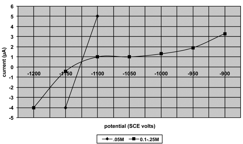
Fig. 7: I – E curves for effect of oxalate on hydrazine oxidation (after Steinmetz et al)
![Fig. 8: ethylenediamine (“en”) vs dep’n rate of Pd (after Steinmetz [29])](https://www.jept.de/wp-content/uploads/2015/05/Jones8.png)
Fig. 8: ethylenediamine (“en”) vs dep’n rate of Pd (after Steinmetz [29])
As indicated above, good process stability was required, and stabilisers were classed as:
a) primary type; As2O5 or KIO3, which act as oisons for homogeneous catalysis of N2H4 oxidation and so control decomposition of the bath, and
b) secondary type; such as imidazol or Pb or Cu salts, which control metal deposition i. e. heterogeneous catalysis.
It was found that As2O5 worked well with all 3 metals, KIO3 is good with Pd; imidazol was an effective secondary stabiliser and avoided heavy metal contamination, being the heterocyclic compound C3N2H4.
Work on optimising the Pd bath showed that the deposition rate was not overly sensitive to the ratio of Pd to ethylenediamine; a Pd concentration of 0.018–0.18 M and 1–3 M ethylenediamine gave good results. Oxalate ions limit deposition rates if concentration is too high. Temperature and pH have major influence on deposition rate and stability; if hydrazine level is high, temperature and pH must be low, and vice-versa. The optimised formula for the Pd and Pt baths are shown in Table 7.
![Tab. 7: Optimised Pd & Pt Baths (from Steinmetz et al. [28])](https://www.jept.de/wp-content/uploads/2015/05/tab-71.png)
Tab. 7: Optimised Pd & Pt Baths (from Steinmetz et al. [28])
In the patent [30] also published by Steinmetz et al (derived from [28]), the oxalate content is stated to be 0.19 M.
Deposit properties for Pd – no physical data are given for Pt:
Assay / 99.9 % Pd
H2 / 127 ppm
N2 / 723 ppm
Hardness / 180–290 HV
Deposits are said to be dense and very ductile.
3.6. Investigations by Chou, Manning & Chen
Chou, Manning & Chen [31] reported on the deposition of thin (circa 100 nm) electroless Pd on hydrogenated amorphous silicon, using a Pd tetrammine complex with hypophosphite as reducing agent. Four variations of a Pd bath were used, containing either citrate, NH3-NH4Cl, EDTA, or TEA as ligands. The field of use is clearly micro-electronic devices.
The a-Si:H substrates were etched in 5 % HF to remove oxides, then activated in a solution containing 1 ml HF, 100 mls acetic acid, 100 mls deionised water; and 0.04 g PdCl2 dissolved in a small excess of HCl (see section 2.2 on activation). The immersion time is 30 seconds and rinse before transfer to plating bath for 5 minutes.
Pd deposits from the citrate bath exhibited bare spots and micro- or even macro-cracks; from the NH3-NH4OH bath deposits are more uniform and crackfree. Deposits from the EDTA or TEA baths had similar morphology; a smooth coherent inner layer, with upper layer of discrete, randomly distributed larger particles. The bath with EDTA produces round smooth particles; that with TEA, agglomerated nodules. Co-deposited P varied from 14 at.% for the EDTA bath to a low of 2–3 at.% for the TEA bath. The EDTA & TEA formulations are shown in Table 8.
![Tab. 8: EDTA & TEA formulations (from Chou et al [31])](https://www.jept.de/wp-content/uploads/2015/05/tab-8.png)
Tab. 8: EDTA & TEA formulations (from Chou et al [31])
N.B. There is no indication in this paper as to the volume into which the components (above) should be dissolved. The later publication by Chou & Chen (see Tab. 9 in section 3.6 following) gives concentrations of 5 x the figures in Table 8. The writer has added the italicised note re final volumes, as being justifiable.
* The writer cannot identify the palladium compound cited above; Pd(IV) tetramminodinitrite [Pd(NH3)4](NO2)2], is perhaps intended; rather more plausible too.
** There is also a difficulty with the trivial acronym “TEA”; the authors refer to this as triethyleneamine, which would be (CH2:CH2)3N, and seemingly highly flammable. Several other compounds are referred to by the confusing acronym TEA also; but the most likely one for use in electroplating and electroless baths is triethanolamine, (HO.CH2.CH2)3N, frequently referred to as “TEA”. This is a useful complexing and buffering additive in many plating processes, not least for scavenging Fe and Al; accordingly the writer suggests it be tried first if evaluating the processes summarised here.
3.7. Investigations by Chou and Chen
Chou & Chen [32] reported on the effects of boric acid and dissolved O2 on the morphology of electroless Pd films from baths similar to those employed by Chou et al [31], Table 9 gives the established optimum compositions used by the authors.
![Tab. 9: EDTA & TEA formulations (from Chou & Chen [32])](https://www.jept.de/wp-content/uploads/2015/05/tab-9.png)
Tab. 9: EDTA & TEA formulations (from Chou & Chen [32])
N.B. This Table gives the component concentrations. However, the writer‘s comments as to Pd tetrammine dinitride* and TEA** remain.
The EDTA bath; additions of boric acid at in-creasing concentrations of 4, 8, 16, and 40 g/l H3BO3 gave a general improvement in coverage and deposit quality, in terms of finer, denser particles as seen in SEM images.
The TEA bath; an addition of 4 g/l H3BOv gave reduced deposit density, with larger and roundernodules randomly distributed – i. e. worse.
Nitrogen sparging – to remove dissolved O2 from the solution – appears to improve deposit quality in both EDTA and TEA baths. The authors give a detailed analysis of likely partial reactions when O2 is present; anodic dissolution of Pd in parallel with reduction of Pd++ to Pd0 is probable.
3.8 Investigations by Hyland
Hyland[33], in his PhD thesis upon electroless deposition of palladium and ruthenium, described his development of an electroless Pd-B process. The optimum process parameters were found to be:
Pd(II) 0.36 g/l
Na2EDTA 6.0 g/l
H3BO3 10 g/l
DMAB (dimethylaminoborane) 0.55 g/l
pH (NH4OH) 10.5
Temperature 22 °C
These parameters are critical; small deviations lead to premature decomposition.
Coatings of ca 1 µm are produced in 10 hours, the deposits are bright, coherent, and adherent,containing 1.4 % boron by weight. SEM scans of a number of trials ranging from 0.3 to 2.7 µm Pd exhibit cracking which may be indicative ofinternal stress, or mishandling of the specimens. Hyland found nitrogen sparging to remove dissolved O2 causes decomposition of the plating solution; itis interesting that Chou & Chen (see section 3.6) found the opposite result, i. e. an improved deposit quality from de-oxygenation and apparently no adverse stability noted. This is may be related totheir using hypophosphite as reducing agent, as opposed to the DMAB used by Hyland.
3.9. Investigations by Nawafune
Nawafune [34] et al reported an electroless palla-dium bath employing phosphite (not hypophosphite) as the reducing agent. The process is quite simple, as can be seen from the parameters below. This is one of the few cases of using phosphite specifically as reducing agent in an electroless plating bath, of which the writer is aware.
The optimum parameters were found to be:
PdCl2 0.01 mol/l
Ethylenediamine 0.08 mol/l
Thioglycollic acid 30 mg/l
Na2HPO3 0.02 mol/l
pH 6
Temperature 60 °C
The deposition rate peaked at 1 mg/cm2/hr at 0.02 mol/l Na2HPO3; as the reducing agent concentration was increased, so the deposition rate reduced, becoming a constant 0.25 mg/cm2/hr at 0.05 mol/l Na2HPO3 and above.
N.B. (1) There is a discrepancy between the authors’ description of their graph for Na2HPO3 vs. deposition rate, and the graph as printed. The writer has not resolved this problem, and thought it best to omit a potentially inaccurate graph for this parameter. (2) 1 mg Pd/cm2 is a thickness of 0.83 µm, notcorrecting for density variation.
The P content of these deposits was much lowerthan when using hypophosphite, approaching a constant value of 3.5 to 4 % P for phosphite concentrations of 0.5 mol/l and above; see Figure 9. This concentration is about 25x higher than the suggested optimum value for Na2HPO3, and the deposit, even at the highest hardness of 950 HV contains only1.55 % of phosphorus. See Figures 10 and 11 for hardness values as deposited, and after heat treatment. Accelerated performance tests show thatelectroless Pd-P with low P content offers not only higher hardness than gold, but comparable goodsolderability and contact resistance. The writer wonders if this apparently attractive process has quite simply been overlooked?
![Fig. 9: P % vs phosphite concentration (after Nawafune et al [34])](https://www.jept.de/wp-content/uploads/2015/05/Jones9.png)
Fig. 9: P % vs phosphite concentration (after Nawafune et al [34])
![Fig. 10: phosphite concentration vs Pd-P hardness and P % in deposit (after Nawafune et al [34])](https://www.jept.de/wp-content/uploads/2015/05/Jones10.png)
Fig. 10: phosphite concentration vs Pd-P hardness and P % in deposit (after Nawafune et al [34])
![Fig. 11: Effect of heat treatment for 1 hr (after Nawafune et al [34])](https://www.jept.de/wp-content/uploads/2015/05/Jones11.png)
Fig. 11: Effect of heat treatment for 1 hr (after Nawafune et al [34])
A patent [35] was granted to the authors of thepaper discussed here; in addition to the formulation shown above, this patent includes two more, very similar formulations employing either hypophosphite or dimethylaminoborane (DMAB) as the reducing agent. Additionally, there are two variants for electroplating palladium, should this be desired.
3.10. Investigations by Uchida et al
A paper by Uchida et al on the depositionmechanism of electroless Pd plating, using formic acid as the reducing agent appears interesting; but it is in Japanese. The solution composition is deducible as being:
PdCl2 / 0.01 mol/l
Ethylene diamine (“en”) / 0.08 mol/l
HCOOH / 0.2 mol/l
pH / 6
Temperature / 60 °C
This is very close to the compositions used by these authors, as described in section 3.8 above. Alsogiven is a solution of 0.1 mol/l PdCl2 plus 0.3 mol/l “en”, which is perhaps a replenisher concentrate. Similarly, a solution of 1.8 mmol/l Na2CO3 plus1.7 mmol/l NaHCO3 is most likely a pH buffer? Performance curves suggest a plating rate of about1.5 mg Pd /cm2/hr is possible (i. e. about 1.2 µm Pd per hour). The writer located a patent (US 5882736 –1999) which appeared to be for a similar formulation; it probably does includes similar compositions among its 20 examples, so varied are they.
4. “ENIG” and “ENEPIG”
What do these unlovely acronyms signify?
Electroless Nickel Immersion Gold – hence ENIG, and Electroless Nickel Electroless Palladium Immersion Gold – conveniently ENEPIG.
These finishes are primarily, if not wholly, used on microelectronics components and the printed circuit boards (PCBs) upon which they are mounted anda totally reliable solder attachment – using lead-free solders – is essential.
Please remember, in English there is a crucial difference between a “lead”, an electrical connection of some sort, and “lead” the metallic element Pb, atomic number 82. Further confusion lies in the use of a substantial proportion of Pb in “solder” formany other purposes. Sometimes the context makes all clear – sometimes not.
4.1. ENIG
ENIG developed in response a demand from the electronics industry for flat surface pads on which to solder discrete solder-mount components; thesepads stand slightly proud of the solder mask. Bear in mind that the circuitry on PCBs is copper, and requires a barrier layer of Ni before solderingcomponents on it. Electroplating with nickel produces variations (edge build-up) in deposit thickness across both PCB and on every individual pad; the misalignments this causes are now totally un-acceptable, especially for very large scale device mounts. Electroless nickel produces a completely uniform, i. e. a plane deposit, when correctly operated.
However, nickel surfaces quickly become passive; this and other restrictions, e. g. need to use non-corrosive non-acidic flux and lead-free solder, caused the adoption of immersion gold over-plating. The high costs for electroless Ni and especially for Au, were justified by better quality – plane mounting – and reliability. Fortunately, a gold deposit of only 0.1µm was not so formidable in 1988. The reasons for choosing gold are its nobility, excellent solder-ability and very rapid dissolution in liquid solders.
Immersion gold processes had been well developed many years earlier, for protection of bare Cu or Ni surfaces of PCBs. These are displacement reaction processes – see section 2.1 above – typically comprising potassium gold cyanide, a citric acid-ammonia buffer, and EDTA acid.
The reaction is simply
2Au+ + Ni0 → 2Au0 + Ni++
where the EDTA and citric acids dissolve nickel and, by stripping electrons from Ni atoms, drive depo-sition of Au as in the equation above.
For deposition of gold on to nickel, the operating parameters are usually about:
Au / 2–4 g/l
pH / 4–6
Temperature / 90 °C
Deposition rate / 0.05 µm/10 min.
Problems are likely to be met when using a complex series of operations; solder joint adhesion failure is the ultimate fault, of course. The writer in his time encountered problems in ENIG PCBs very oftendue to some of the following selection: over-specifiedAu thickness (e. g. demanding 0.2 µm of Au ormore); use of excessive process times, to meet over-specified Au thickness – causing general corrosionof substrate, and especially pitting via porosities;undercutting of Au deposit and a consequentpassivity of the nickel; faults in electroless nickel processes producing too high P or variations in NiP layer causing thin or porous areas in the Au coating.
Examination of pads on unused parts of knownfaulty PCBs by tape pull reveals poor adhesion and “black pad” readily visible on the NiP surface.
Fang [37] observed that the longer the time (andthus the thicker the Au deposit) in the displacement Au process, the worse the problem.
Walsh [38] considered the gold bath not to be the problem. It is rather, due to the electroless NiP bath, and particularly certain of the additives used inolder formulations (it is interesting that lead, sulphur compounds, and cadmium, all well-known troublemakers, were and are still frequently used additives in NiP baths).
Endres & Horvath [39] survey the subject of ENIGin detail; and suggest the number of metal turnovers in electroless NiP is related to this corrosive attackon pads (Endres has elsewhere suggested dis-carding the NiP bath at 3 metal turnovers). The authors noted this corrosive attack also occurs atthe interface between pad & resist; this is often a crevice normal to the PCB plane and ideal forpromoting such highly undesirable activity.
Goosey [40] announced the formation of ASPIS, a 12-member group primarily in European locations, to research ENIG solderable finishes for PCBs. The body of this article includes some of the problems encountered with ENIG, such as “black pad” and porosity of immersion gold, in the field.Regrettably, ENEPIG is not mentioned and as aconsequence, nor is the dichotomy between it and ENIG. Nevertheless, this is useful reading matter.
4.2. ENEPIG
ENEPIG enters the scene; Yee [41] commented in 2007 that ENIG “continues to offer significantadvantages for applications in mobile phones, keypads and contacts. Despite work undertaken to resolve the issue of nickel pad corrosion by the immersion gold bath, concern remains.” He goes on to say that electroless Pd has been known for quite some time but cost has limited its use. The work reported included pull & shear testing of ball grid arrays, and growth of inter-metallic compound over 1 000 hours. A fair summary of this paper is; “ENEPIG with low thickness Pd 0.05-0.1 µm –good: ENIG, and ENEPIG with high Pd thickness0.2 to 0.3 µm – both are poor”.
Yee’s paper indicates the earlier but rapidly growinginterest in ENEPIG; a sequence of electrolessnickel – as a barrier layer between copper circuitry and the eventual solder applied to hold and connect electronic devices; then electroless palladium –as a barrier to prevent corrosion of the electroless nickel by an immersion gold bath; immersion gold is applied to provide a surface readily and rapidly soldered – in this situation gold dissolves in molten solder very rapidly. And yet this concatenation works well; as the papers briefly reviewed below show.
A quite extensive evaluation of the ENEPIG process for solder joints and for wire bonding was reported by Chun-Hsien Fu et al [42] (2008), in which they compared ENEPIG performance in wire-bonding and solder joints with electrolytic Ni/Au – the latter having been the benchmark for microelectronics bonding for many years, but becoming less suitable as miniaturising accelerates.
Their introduction notes that ENIG is popular in industry but causes weak wire bonds and solder joint problems; if the Au deposit is too thin, wire bonds are weak, whereas solder joint problems are related to black pad issue discussed above. Black pad, the authors explain, is caused by nickel oxide deposition underneath immersion gold deposits by the displacement reaction – Au atoms replacing Ni atomscreating porous structure leading to galvanic corrosion. (There is a mismatch in atomic dimensions – the atomic radii are Au 1.44, Ni 1.25 respectively;the equation in section 4.1 above shows, two Au atoms are deposited for one Ni atom removed.)
Test finishes were:
- electrolytic: Ni 5 µm/Au 0.5 µm
- ENEPIG: Ni 5 µm/Pd 0.2 µm/Au 0.1 µm
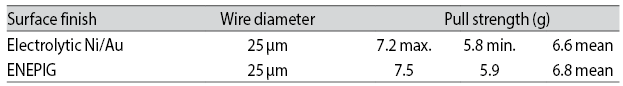
Wire-bond pull tests show ENEPIG to be surprisingly good for only 0.1 µm gold.
Comparison trials of solder joint performance after multiple reflow, or 150 °C ageing up to 1 000 hours (ball grid arrays, standard & cold shear, high speed shear), showed ENEPIG to be generally as good as if not better than, conventional plating. Failure mode analysis – was fracture within the solder or inter-metallic compound (IMC) layer – confirmed ENEPIG to be quite as good.
A similar study, but of wire-bonding to ENEPIG surfaces, by Yee, Leung & Bayes [43] in 2009 was concerned exclusively with wire-bonding, com-paring electrolytic Ni 3 µm/Au 0.25 µm as the substrate finish, vs. ENEPIG test matrix of ENi 5 µm/EPd 0.05–0.4 µm/Imm‘n Au 0.03–0.15 µm. Theconclusion was that ENEPIG is a viable alternativeto electrolytic Ni/Au.
In the test series with Au 0.03 µm, the thicker the Pd deposit, the better the failure mode result, in-dicating formation of a good Au-Pd alloy; in the case of thin Pd deposits of 0.05 and 0.1 µm, an improved result was noticed with heavier gold at > 0.05 µm. It seems a mutually protective synergy exists between Au and Pd; perhaps thermosonic bonding has a greater tolerance than the writer ever knew.
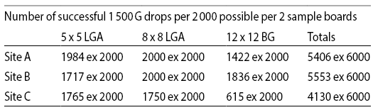
Another interesting comparison of “traditional” electrolytic Ni/Au with ENEPIG processed circuit boards, this time for hand held devices (mobile phones), employed “drop testing” where the soldered assembly is subjected to repeated 1 500 G shockloading until failure or 200 drops. The conclusionby Ahn et al [44] was that ENEPIG was comparable to the electrolytic control boards, with understandable reservations; field tests at three dif-ferent manufacturers showed quite wide variationsin number of drops to failure. The totals are shown here by test array and manufacturer: there does seem to be a need for an experimental design to locate which operations are out of control.
Another interesting (and overdue) comparison of ENIG with ENEPIG, in this case when heat stressis applied, is given by C.C. Lee et al [45]. Theauthors helpfully review why we need these complex finishing processes; it’s for lead-free, reliablysolderable pads on PCBs, chip mounts and otherelectronics necessities. A prime requirement is for excellent solderability allied to long shelf life;heating is generally considered to be a method of accelerating normal ageing, and particularlyappropriate where a short heating pulse to 300 °C (twice for double sided substrates) is part of the usual service life for these components.
The authors found that heat treatment produced nickel oxides on ENIG surfaces, where no oxides were before; nickel oxides are stable, adheretenaciously, and will prevent wetting by solder even with powerful flux, which is not permitted because of corrosive effects. To assess the oxidation quantitatively, sample coupons of ENIG & ENEPIG were heated (annealed) at 150 °C for 200 hrs. UsingAuger electron spectroscopy (AES) and Secondary ion mass spectrometry (SIMS) techniques, it was found that
a) ENIG samples had a continuous coating of nickeloxides even before heating; this coating grew thicker when heated (annealed) as above. SIMS showed the oxide coating consisted of NiO and NiO2
b) ENEPIG samples also had a continuous coatingof oxides, containing both Ni and Pd oxides, which grew thicker when heated. However, this oxide layer was thinner than on ENIG. The SIMS results showed this film contained NiO, PdO, and PdO2.
5. List of patents
Some few of the many patents for electroless palladium processes, not otherwise discussed but which the writer thought perhaps of interest, are listed here in date order:
|
1971 |
JP71001244 |
uses hydrazine sulphate as reducing agent |
|
1980 |
DE2841584 |
hypophosphite & hydrazine |
|
1984 |
JP59080764 |
uses hydrazine as reducing agent |
|
1984 |
US4424241 |
uses formaldehyde (HCHO) or formic acid (HCOOH) |
|
1988 |
DE3790128 |
uses hypophosphite as reducing agent |
|
1989 |
JP91001382 |
uses phosphite as reducing agent |
|
1989 |
JP1268877 |
contains amines, sulphur, phosphites |
|
1992 |
JP3287781 |
for electroless Pd-Ag alloy |
|
1993 |
JP5214551 |
electroless Pd-Ni alloys, using hypophosphite & borohydride |
|
1993 |
EP526334 |
hypophosphite & any of twenty amines |
|
1996 |
JP8269727 |
uses phosphinate or phosphite, borohydride, aminoborane |
|
2006 |
WO2006112215 |
describes displacement Pd 0.2 to 10 nm (i.e. not chemical reduction) |
|
2007 |
WO2007010760 |
contains bismuth as stabiliser |
|
2010 |
JP2010196121 |
contains ethylene diamine; claimed to be very stable |
|
2010 |
JP2010261082 |
hypophosphite & formic acid |
6. References
- “Theoretical density” from Physical properties of the preciousmetals; Engelhard Industries, Sutton, Surrey, U.K. 1965
- Based on market prices, Daily Telegraph, London, U.K. March 2012
- Everyman’s Encyclopedia, JM Dent, London, 1958
- CR Hammond, Hbk of Chemistry & Physics, 81st Edn. 2004, CRC (Chemical Rubber Corp’n.)
- Platinum Metals Review, Vol55, Iss3, pp201-2. July 2011
- DF Shriver & PW Atkins, Inorganic Chemistry 3rd Ed. OxfordUniversity Press, 2002. Cf. pp264-5
- RG Baker, Connectors ‘89, East Midlands Branch, Institute ofMetal Finishing, Birmingham UK, pp8-13
- Based on JR Partington, General & Inorganic Chemistry,MacMillan, London, 1951
- RW Johnson, J. Electrochem. Soc. 108 pp. 632-5, 1961)
- RN Rhoda, Plating, 50 (1963) 307-309,
- GB 872785 (1961) to Engelhard Industries
- T Jones, “Electroless Platinum Plating”, Jahrbuch Oberflächen-technik, 61 (2005) 18-30, Eugen G. Leuze verlag, Bad Saulgau, Germany
- A Brenner & GE Riddell, J.Res. Nat. Bur. Stands, 37, 31, (1946); Proc. Am. Electropl. Soc. 33, 23(1946)
- A Brenner, Metal Finishing, 52 (1954) 68-76, 52 (1954) 61-68
- GO Mallory & J Hajdu, Electroless Plating :Fundamentals &Applications, AESF pub. Orlando, Florida, USA 1990
- JN Keuler, L Lorenzen, RN Sanderson, & V Linkov; Plating & Surface Finishing, 84 (1997), 8, 34-40
- N Feldstein, M Schlesinger, NE Hedgecock, SL Chow; J Electrochem. Soc. 121 (1974) 6, 738-744
- A Burelli, Galvano-Organo, 9 (1979) 498, 667-670
- RN Rhoda, Trans IMF 36 (1958-9), 82-85
- RN Rhoda, J Electrochem. Soc. 108 (1961) 7, 707-8
- RN Rhoda, J Electrochem. Soc. 109 (1962) 8, C205
- F Pearlstein & RF Weightman, Plating, 56 (1969) 1158
- Y Okinaka & C Wolowodiuk, Ch.16 of Electroless Plating:Fundamentals & Applications. Edited GO Mallory & J Hajdu, pub. AESF, Orlando, Florida, USA, 1990
- I Ohno, Ch.20 of Modern Electroplating, 4th edn. EditedM Schlesinger & M Paunovic; John Wiley & Son, London & New York, 2000
- H Ocken, BG Pound, & DH Lister, Thin Solid Films, 171 (1989), 313-322
- Toluene is Highly flammable, and Harmful by inhalation. Safermaterials are readily available; consult a cleaning specialist.
- SN Athavale & MK Totlani, Metal Finishing, 87 (1989) 23-27
- P Steinmetz, S Alperine, A Friant-Costantini, & PJosso, Surface & Coatings Technology, 43/44 (1990) 500-510
- US 4844739, 1989
- EP 423005 (1991)
- ML Chou, N Manning, & H Chen, Thin Solid Films, 213 (1992) pp64-71
- ML Chou & H Chen, Thin Solid Films, 208 (1992), 210-216
- Lee Hyland, Ph.D. Thesis on Electroless Deposition of Group 8Metals: University of Hull, UK, 1995
- H Nawafune, S Mizumoto, M Haga & H Uchida, Trans.IMF,(1996), 74 (1), 21-24
- DE 4201129 (1992)
- E Uchida, T Okada, H Nawafune, S Nakao, & S Mizumoto,J.Fin.Soc.Japan, 50, 5 (1999) 469-470
- JL Fang, Plating & Surface Finishing, (2000) 88 (7) 44-7
- M Walsh, Galvanotechnik, (2002) 93 (9), 2281-86
- B. Endres & F Horvath, PLUS, 5 (2002), 5 703-710
- M Goosey, TransIMF, 89 (2011) 2 65-7
- DKW Yee, 3rd IMPACT Conference Proceedings, 2007, Taipei,Taiwan, pp208-218
- C-H Fu, L-Y Hung, D-S Jiang, C-C Chang, YP Wang, CS Hsiao, 2008 Electronic Components & Technology Conference, IEEE, pp1931-35
- DKW Yee, SL Leung, & M Bayes, 4th IMPACT Conference Pro-ceedings, 2009, pp629-632
- J Ahn, H Kim, K Byun, Y Lee, D Jang, & B Kim, Proc. ASME 2009 Conference, IPACK 2009, San Francisco, CA, USA. pp929-935
- CC Lee, HY Chuang, CK Chung, & CR Kao, 5th IMPACT Con-ference Proceedings, 2010, pp1-4
PDF Version of the article |
Flash Version of the article |
|
| [qr-code size=”2″] | ||